 HOME
HOME
|
|
CATALOGUE
|
|
CONTACT US
|
|
DELIVERY
|
|
|
|
|
|
|
to view manuals downloaded from this site you require

|
|
|
|
|
|
|
|
|
$169.90
Prices are in Australian dollars

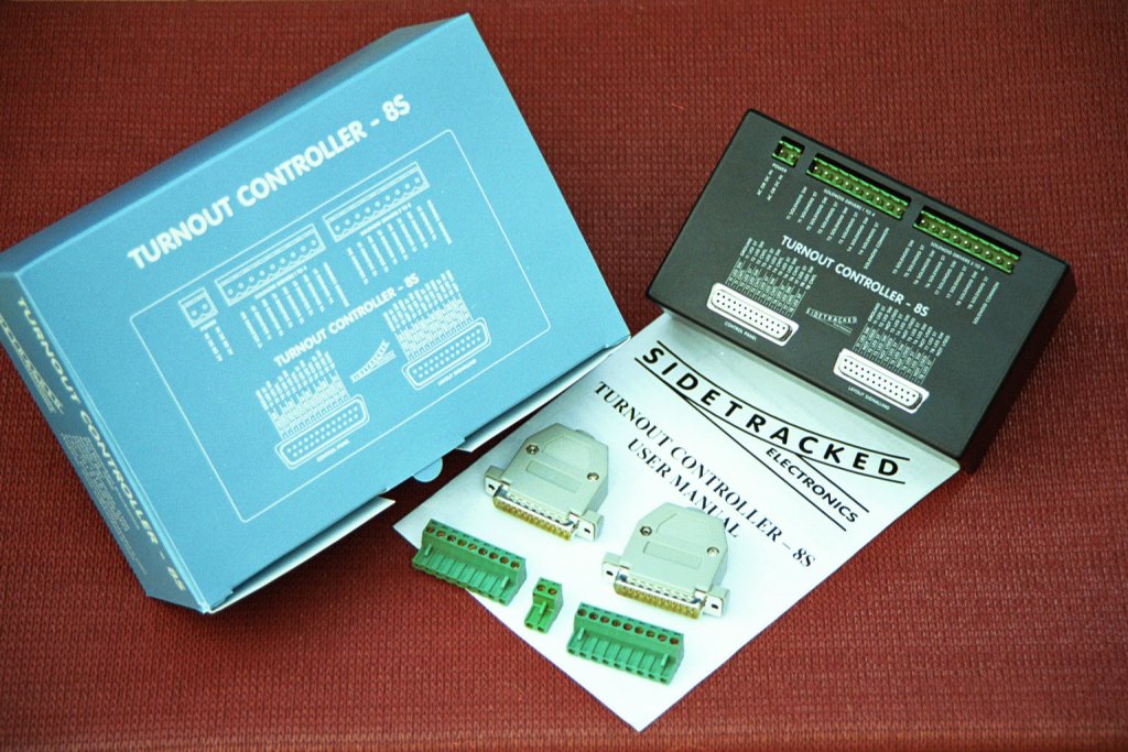
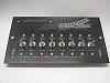
The TC-8S controls up to eight turnouts on your layout, signal lighting associated with each turnout as well as the lighting on your control panel.
In conventional wiring, to operate each turnout you would have two push button switches on your control panel. One side of each switch would be wired to your Capacitor Discharge Unit (CDU) and the other side of would be wired to your turnout motor. The problem with this method is that:
1) you need two wires and two switches to control each turnout
2) the wires have to be thick enough guage to ensure that there is no voltage drop
3) the heavier guage wire makes wiring of control panels difficult and
4) the switches only your control panel wear out due to arcing when activated.
The TC-8S solves all these problems plus gives you a range of new features all in the one unit.
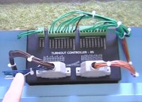
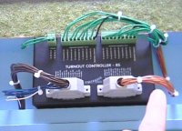
TURNOUT MOTOR WIRING
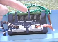
With the TC-8S your turnout motors are wired directly to the unit.
There are two 9 way connectors along the top of your TC-8S which are used to connect to your eight turnout motors.
Each connector operates four turnouts.
There is a common wire (black) which goes to all turnout motors
and then each turnout motor has an additional two control wires (green) to move it from side to side.
An inbuilt CDU ensures that your solenoids will not burn out.
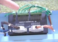
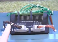
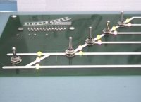
CONTROL PANEL WIRING
One of the main features of the TC-8S is its simplified wiring for your control panels.
There is a common wire (white) which goes to all the toggle switches on your control panel.
Then from each toggle switch you wire to a turnout control pin on the TC-8S (blue).
Each turnout has a single control pin on the TC-8S. A single wire to a control pin is all that is needed to operate each turnout.
In the case where you have a crossover and you wish both turnouts to operate from the same switch,
it's simply a matter of connecting their control pins together at the TC-8S and then running a single wire
to a toggle switch on your control panel.
You can operate as many turnouts as as you like from the one switch, simply by connecting their control pins together.
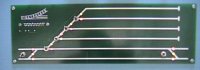
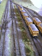
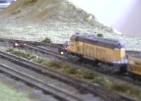
In this example layout there are eight turnouts used.
There is two crossovers on the main line requiring only one wire to control each one,
and four individual turnouts to control the switching in the yard.
That is a total of six control wires (blue) and one common wire (white) to control eight turnouts.
All control wiring to operate your turnouts is low voltage and low current.
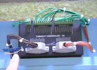
CONTROL PANEL INDICATORS AND LAYOUT SIGNALLING WIRING
You can wire as many sets of Light Emitting Diodes (LEDs) to each turnout as you like.
This allows wiring of bi-colour LEDs on your control panel so that train routes can be easlily recognised.
All Lighting is multiplexed,
this means that the LEDs are switched on and off at such a fast rate that they all seem to be on at the same time.
This reduces the current consumption of your layout quite considerably if you have alot of lighting.
The brown wires indicated are for the operation of lighting on your control panel.
The orange wires indicated are for the operation of signal lighting on your layout.
It is not neccessary for either control panel indicators or layout signal lighting to be wired to the TC-8S for it to function correctly.
Lighting can be wired in at any stage.
POWER

The TC-8S can be powered by either 15 to 25 Volts DC or 12 to 18 volts AC.
OTHER FEATURES
The TC-8S has a synchronise feature.
When your layout is not in operation and your turnouts get knocked
or someone accidently changes a switch on your control panel so that your turnouts and control panel no longer match.
The TC-8S will go through a synchronisation process when you power it up where it will switch all the turnouts
back and forth until they match your control panel again.
Whenever more than one turnout is to be activated at the same time, i.e when you wire a crossover from a single switch,
the TC-8S switches each turnout in sequence giving the CDU time to fully recharge before pulsing the next motor.
This ensures that each motor gets a full supply of power to operate the turnouts correctly.
TC-8S User Manual (184K)
TC-8S Wiring Diagram: Control Panel without Indicator LEDs (64K)
TC-8S Wiring Diagram: Control Panel using Tri-Colour LEDs (72K)
TC-8S Wiring Diagram: Layout Signals using Dual LEDs (68K)
All parts in the TC-8S Wiring Diagrams can be purchased on-line by clicking on the "Sidetracked Electronics Code" on the downloaded file.
|
|
|
ASSOCIATED
PRODUCTS
|
|
|
TURNOUT CONTROLLER - 8S CONTROL PANEL
$59.50 More Info...
OUT OF STOCK
|
|
|
CABLE, 25 PIN MALE TO 25 PIN FEMALE, 1.8M LENGTH
$14.95 More Info...
OUT OF STOCK
|
|
|
|